0 10 Dimming Ballast Wiring Diagram
45+ 0 10 Dimming Ballast Wiring Diagram
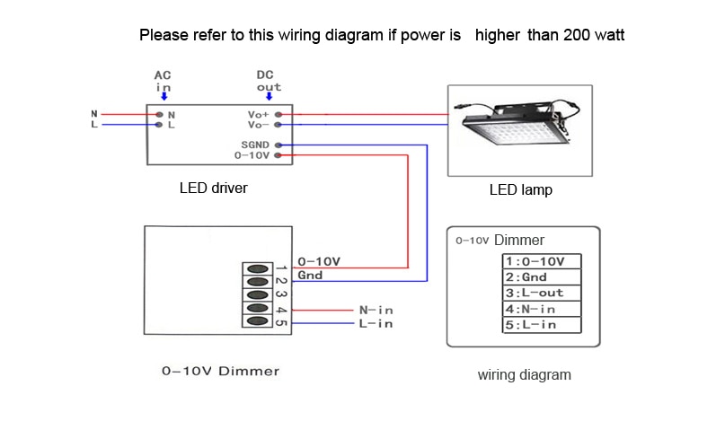
Pics. Simply put, the control signal is a dc voltage that varies between zero and ten volts. It shows the elements of the circuit as simplified shapes, and also the power and also signal connections in between the devices.
Block diagram of the digital dimming electronic ballast.
This ballast control ic provides all of the. 3 wiring diagram note : take the connection of channel 1 as an example. 1 typical dimming system for incandescent lamps. Figure 4 shows the block diagram of a formal cfl.

Belum ada Komentar untuk "0 10 Dimming Ballast Wiring Diagram"
Posting Komentar